Robo Arm
A servo-driven robotic arm.
- Arduino
- Servos
- 3D printing
- COMMITS
- 7
- FIRST
- Aug 2021
- LAST
- Oct 2026
- ACTIVE MONTHS
- 4
Robo-Arm

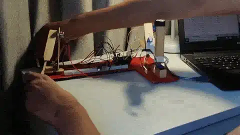
A desktop robotic arm you drive by hand. Move a small "shadow" copy of the arm and the real one mirrors it, joint for joint, in real time. No app, no joystick, no path planning: the controller is a second arm built from potentiometers, so steering it feels like moving the robot itself.
What it does

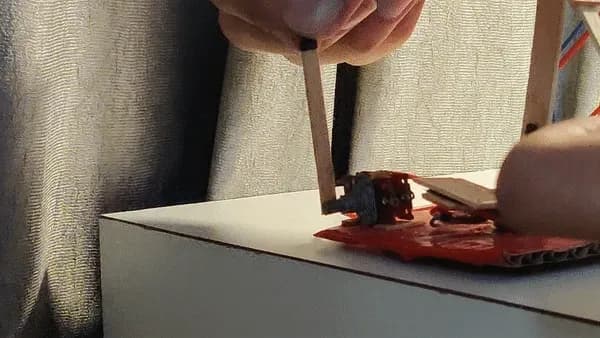
- Mirrors your movement. The shadow arm's joints are potentiometers. Rotate the base, raise the arm or close the claw on the controller and the robot does the same.

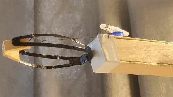
- Grips things. The end effector is a working claw, so the arm can pick up and set down small objects.
- Runs off a single USB cable. The whole system, three servos included, is powered from the Arduino's 5 V rail.
- Stays steady. Readings are clamped and thresholded before they reach the servos, so the arm holds its pose instead of twitching with sensor noise.
There is a full clip of the arm in action in Video/VIDEO.mp4.
How it works

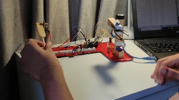
shadow arm (3 potentiometers) → Arduino ADC → clamp + map → 3 servos (base, arm, claw)Each joint on the shadow arm is a potentiometer. The Arduino reads all three on its analog inputs, clamps each reading to the range that joint can physically reach, maps that range onto the servo's angle, and writes the angle to the matching servo. The loop runs continuously, so the robot tracks the controller with no visible lag.
Degrees of freedom
Three servos, three movements:
| Joint | Servo pin | Pot input | What it does |
|---|---|---|---|
| Base | 10 | A0 | Rotates the whole arm left and right |
| Arm | 9 | A1 | Raises and lowers the upper segment |
| Claw | 8 | A2 | Opens and closes the gripper |
Precise control
Potentiometers are noisy and the ones on the shadow arm only sweep part of their travel. The sketch deals with both: each raw reading (0 to 1023) is clamped to the window that joint actually uses, then mapped onto the servo range for that joint. Anything outside the window is pinned to the nearest edge, so a wobbly reading at the end of travel never throws the servo past its limit.
Power and wiring
Three 9 g micro servos run straight from the Arduino's 5 V output. The shadow arm connects over plain jumper wires: three signal lines, 5 V and ground. Nothing else is needed.
End effector
The claw is a repurposed hair clip on a popsicle-stick mount, driven by the third servo. It opens wide enough for small objects and closes with enough grip to lift them.
The build
The frame is popsicle sticks and hot glue, with the servos sunk into the joints. The base servo sits in a wooden block so the whole arm can swing; the arm servo lives at the shoulder; the claw servo is glued to the tip of the upper segment.
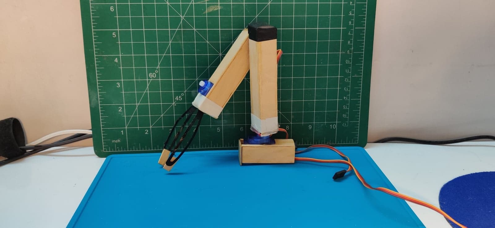
Parts
- Arduino (any board with three analog inputs and three PWM pins; the build used a Mega)
- 3 × 9 g micro servos
- 3 × potentiometers for the shadow arm's joints
- Popsicle sticks, a hair clip, a small wooden block, hot glue
- Jumper wires
The code
Everything lives in Code/RoboArm/RoboArm.ino. It is short on purpose: the whole control loop is read, clamp, map, write.
potx = analogRead(A0);          // one reading per joint
if (potx < minx) potx = minx;   // clamp to the pot's usable window
if (potx > maxx) potx = maxx;
posx = map(potx, minx, maxx, 10, 120);   // window → servo angle
x.write(posx);
The clamp windows (minx/maxx and friends) are the raw ADC values each shadow joint produces at its two ends of travel. Measure them for your own build and update the constants at the top of the file; the serial monitor prints every raw reading at 9600 baud, which is the easiest way to find them.
Build your own
- Clone the repository.
- Build the arm and the shadow controller, then wire the servos to pins
8,9and10and the pots toA0,A1andA2. - Open
Code/RoboArm/RoboArm.inoin the Arduino IDE and upload it. - Open the serial monitor, move each joint on the shadow arm to both ends of its travel, and copy the readings into the
min/maxconstants. - Upload again. The arm now follows the controller.
Repository
Code/RoboArm/RoboArm.ino   the sketch
Images/                    build photo and operation clips
Video/VIDEO.mp4            the arm in action
Ideas for next time
- A fourth servo for a wrist, so the claw can tilt.
- Record and replay: capture a sequence of shadow-arm positions and play it back.
- A sturdier frame so the arm can carry more than a few grams.
HEAD · c948d595 FOLDERS · 9 FILES
- CodeSigned-off-by: Eshaan Yadav <ESHAANYADAV24@GMAIL.COM>Aug 2021
- ImagesSigned-off-by: Eshaan Yadav <ESHAANYADAV24@GMAIL.COM>Aug 2021
- VideoSigned-off-by: Eshaan Yadav <ESHAANYADAV24@GMAIL.COM>Aug 2021
- README.mdrewrite readme around the product: what it does, how it works, the build, the code2h ago
Showing the top two levels. Files aren't browsable: this is a portfolio, not a mirror.
7 COMMITS · 2 AUTHORS
MON, OCT 5 20261 COMMIT
- c948d59rewrite readme around the product: what it does, how it works, the build, the codeClaude2h ago2h ago
WED, JUL 5 20231 COMMIT
- bc2788aUpdate README.mdEYJul 2023Jul 2023
TUE, OCT 5 20214 COMMITS
- ff97315Update README.mdEYOct 2021Oct 2021
- 200a84cUpdate README.mdEYOct 2021Oct 2021
- 0ccc0faUpdate README.mdEYOct 2021Oct 2021
- 9271fa8Create README.mdEYOct 2021Oct 2021
SAT, AUG 21 20211 COMMIT
- 5495be9Signed-off-by: Eshaan Yadav <ESHAANYADAV24@GMAIL.COM>EYAug 2021Aug 2021
That's every commit.